Surface water drainage systems rely heavily on correctly specified channel drains in either plastic (HDPE or PP) or concrete ...
Surface water drainage systems rely heavily on correctly specified channel drains in either plastic (HDPE or PP) or concrete. The channel drain is a crucial part of a drainage system. It also has other names such as trench drain, line drain, slot drain, or drainage channel. A channel drainage system:
- Does not require deep excavation and, in some cases, may remain at ground level;
- Requires only a limited number of components, making transportation and installation relatively easy;
- Is easy to install and modify if needed;
- Eliminates the risks posed by water buildup and stagnant water while being an easy solution with a relatively low cost.
A channel drain system is also long-lasting, easy to maintain, and can help reduce soil erosion. Let's break down the steps and learn how to install channel drains.
The steps needed to complete a channel drain installation:
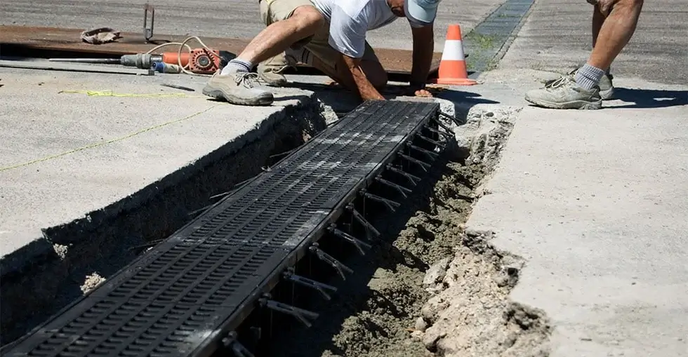
- Dig a trench for the channels. The depth of the excavation will depend on the type and dimension of the chosen channel, plus the height of the layer of concrete on the bottom (see table and diagram below for details). At this stage allowance should also be made for the eventual passage of vertical and/or horizontal outlet pipes, and for the presence of any catch basin for the collection of waste.
- Attach a string line to show the finishing height of the grate (around 5/64" lower than the surrounding surface level). Factor in a minimum 3/16" fall for every 39.4" (5mm for every 1m) of channel drain length (1:200 ratio).
- Lay a concrete base on the bottom of the trench, keeping in consideration any slope for water drainage. The concrete used for the base and later, for the shoulders of the channel, should have S4 fluidity (slump) properties to enable proper filling of all the cavities on the outside of the channel. For this reason aggregates of stones with a maximum diameter of 15 mm (9/16") should be used in the mix. Please note that Dakota channels are not self-supporting, but they become so after the proper positioning and setting of the concrete.
- Install the Dakota channels, when the base layer of concrete is complete, starting from the point of water discharge (downstream) by connecting the output to the sewerage system or, if present, to a wastewater/oil separator for the treatment of the water. The terminal plug must be inserted on the edge of the channel, and the remaining channels must be installed from lowest point to the highest, using the joints on the channels ends. Install sections with their grates in place to allow for height accuracy against the surrounding surface. The final channel can be cut to achieve the desired length. Fit an end cap to the final section. The blocking end cap should always be at the highest point.
- Prior to pouring concrete around the shoulders of the channels it is extremely important that the gratings are fitted to the channels, to avoid potential damage or deformity due to the pressure exerted by the concrete. Always protect the gratings with a plastic film, or heavy duty masking tape, to avoid any cleaning after the concrete has been cast. For the best water-tightness, it’s also possible to utilize a bitumen-based sealant (SHELL TIXOPHALTE, for instance) during the connection of one channel to another. Seal joints and end caps with a silicone sealant to improve durability, leak resistance, and performance.
- Pour concrete to create a 2 mm (5/64") height difference above the grate section of the drainage channels. Wait 72 hours before putting weight on the concrete or moving the drainage channel grates to avoid any damage. Finally, make sure that the surrounding pavement is between 3 and 5 mm (1/8" and 3/16") above the upper edge of the channel or the upper surface of the grating. Remove the protective film or tape and fix the gratings to the channels.
- A final and extra step will be periodic maintainance and cleaning of your drainage channels.


Despite its impactful role in protecting the land around it, people often overlook and underestimate the importance of surface water drainage. Failure of drainage systems is a common occurrence. It is worth considering why some surface water drainage systems fail.
Occasionally, minor installation errors can affect the overall effectiveness of the drainage system resulting in stagnant water build-up, water seepage and eventual flooding. While this can cause significant damage to a building, it can also negatively impact the natural environment surrounding it.
The three most prominent mistakes made during channel drain installation:
1. Planning errors
Good planning and knowing the terrain are important for installing channel drainage without any issues. For example, not following the trench size guidelines can lead to failure of the drainage system.
Not understanding the substrate or miscalculating the slope can reduce flow rates and cause blockages in the system. If in any doubt we suggest talking with a skilled installer about how to install the drainage channels for your specific project.
2. Unsuitable materials
Depending on location drainage pipes can experience a significant amount of weight and pressure from applied loads. This is especially true when vehicles pass over them frequently.
When selecting drainage channels, consider their load capacity, potential temperature changes, and the deterioration of channel integrity over time. There is a wide array and a variety of types of channels available. They come in various materials like concrete, plastic, cast iron, ductile iron, or even stainless steel.
Using plastic channel drains, where concrete channel drains are necessary, may cause the failure of the drainage system. Pay attention to the various types of channel drains and grates and their typical uses. Plastic channel drains have a number of benefits but cannot replace concrete channels where they are needed.
3. Incorrect water flow rate calculation
Incorrect calculation of water output, if under estimated, can lead to choosing smaller channels and pipes. These smaller channels and pipes may not efficiently dispose of the required volumes of surface and foul water. As a result, blockages can occur, causing water to seep into building walls and structures.
Complying with the guidelines
DIN19580 / EN 1433 is a European Standard that categorizes drainage channels based on their use and the strength of their grates, and rainwater drainage regulations in the UK follow similar guidelines. The standard applies to both pedestrian and vehicular areas to ensure the creation of correctly specified surface water drainage systems.
LOAD CLASSES ACCORDING TO THE BS EN 1433 STANDARD
DIN19580 / EN 1433 is the only recognized international standard written specifically for Channel / Trench Drains. It is widely accepted in the United States and worldwide as the benchmark. Dakota drainage channels are manufactured to meet or exceed the required standards.
The standard applies to both pedestrian and vehicular areas to ensure the creation of correctly specified surface water drainage systems.
Grate Design Load of at least:
CLASS A 15
15 kN / 3,372 lbs. load test = 1.5 metric ton / 1.65 US tons
Group 1: Areas that can be used only by pedestrians and cyclists.
CLASS B 125
125 kN / 28,100 lbs. load test = 12.5 metric tons / 13.7 US tons
Group 2: Sidewalks, pedestrian areas and comparable areas, parking for private cars or multilevel car parks.
CLASS C 250
250 kN / 56,200 lbs. load test = 25 metric tons / 27.5 US tons
Group 3: Road curbs and areas not directly exposed to vehicle traffic or similar; commercial parking lots and general commercial areas.
CLASS D 400
400 kN / 89,920 lbs. load test = metric 40 tons / 44 US tons
Group 4: Roads with heavy traffic (including pedestrian streets and parking areas for all types of road vehicles.
CLASS E 600
600 kN / 134,800 lbs. load test = metric 60 tons / 66 US tons
Group 5: Areas subjected to extremely heavy vehicles traffic, for example gas stations, industrial and warehouse roadways and loading bays, etc.
CLASS F 900
900 kN / 202,320 lbs. load test = metric 90 tons / 99 US tons
Group 6: Areas subjected to very high wheel loads, for example docks and airports.
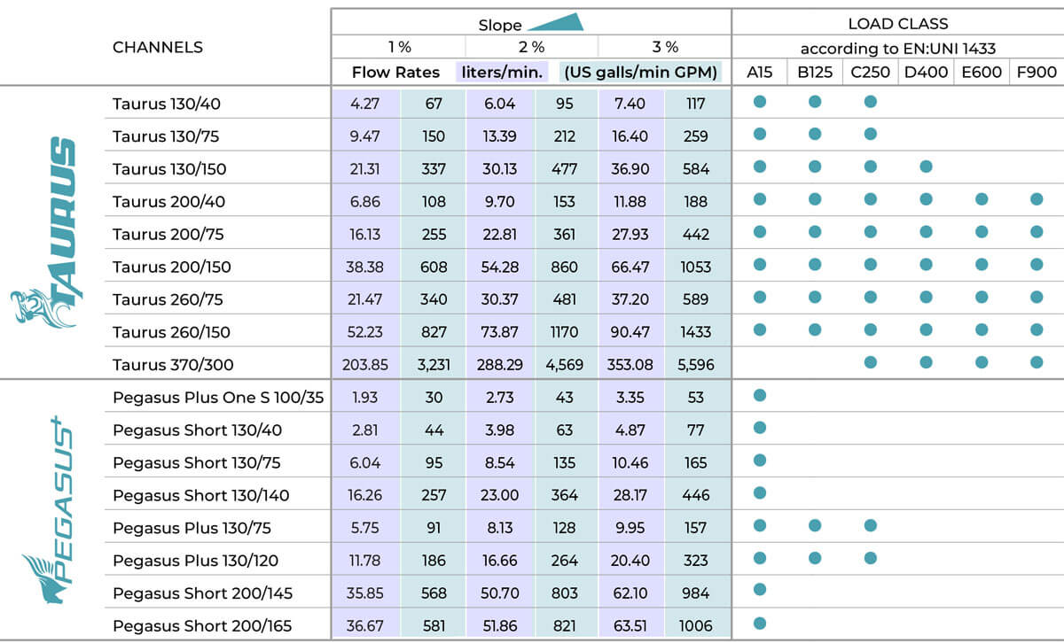
Calculation showing the Dakota Group's Pegasus and Taurus drainage channel Flow Rates and Load Classes:
Dakota Group is a building materials supplier primarily serving the EMEA region. We are now operating the United States as well. As a leading European supplier of building materials, we offer a range of drainage supplies that work together in correctly specified systems. We have established ourselves as a reliable drainage supplier, with over four thousand customers stocking our products.